Introduction
I’ve been working on a flight control system in Rust, and one of the highlights has been implementing PID controllers. What I love about PID controllers is their simplicity: basic math that can tame complex systems, like keeping a drone steady mid-flight. In this post, I’ll guide you through my implementation and the insights I gained along the way.
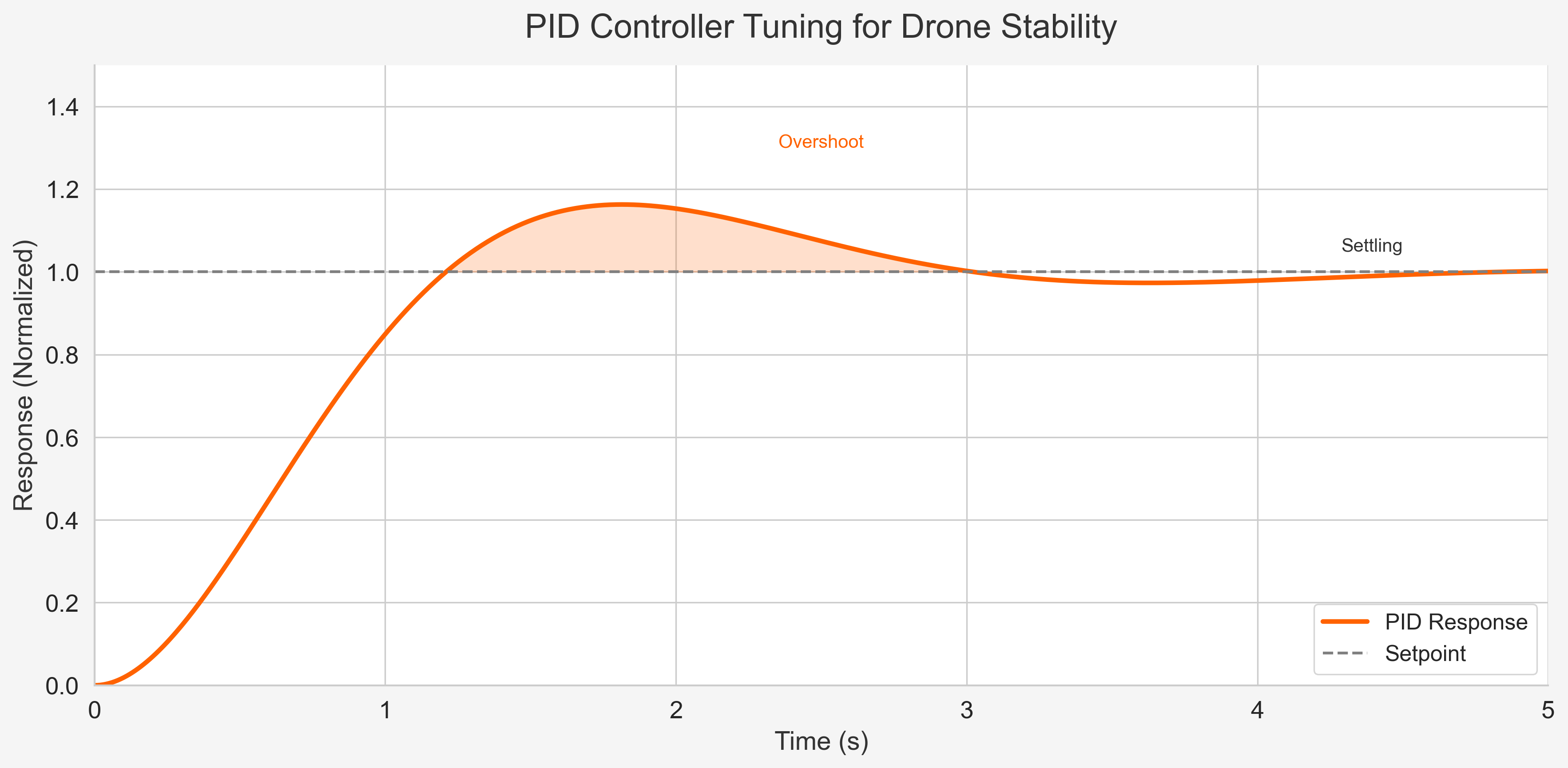
A PID controller (proportional, integral, derivative) constantly measures the error between a system’s current state and its target, adjusting the output to close the gap. Imagine driving a car: if you’re at 30 mph but aiming for 60, you press the accelerator. As you near 50, you ease off to avoid overshooting. That’s PID in a nutshell. For drones, it’s a marvel, stabilizing flight without needing a perfect physics model. Just tweak a few gain parameters, and it adapts to different weights or motor strengths.
The PID Equation
Let’s unpack the magic of a PID controller. Don’t worry: it’s simpler than it seems! Here’s the core equation:
Output = (Kp * error) + (Ki * integral) + (Kd * derivative)
The Output is your command, such as how much to adjust a drone’s motors. It’s built from three terms:
Proportional Term (
Kp * error): The immediate fix.erroris the gap between where you are and where you want to be, like 30 mph below your target.Kpscales the response: crank it up for a big push, but overdo it, and you’ll overshoot.Integral Term (
Ki * integral): The long-term corrector.integralsums past errors, like noticing you’ve been too slow for a while.Kiweighs this history, tackling persistent small errors.Derivative Term (
Kd * derivative): The lookahead dampener.derivativetracks how fast the error changes, like speeding toward 60 mph too quickly.Kdsmooths the approach to prevent overshooting.
In my flight controller, this runs in a 200Hz loop, tweaking motor speeds to hold the drone steady. The challenge? Tuning Kp, Ki, and Kd until it feels right, much like dialing in a perfect guitar chord. Next, I’ll show how I coded this in Rust.
Implementation
Here’s how I brought the PID controller to life. I’ll assume a math library that handles vector operations like:
2 * vec2(1.0, 2.0);     // vec2(2.0, 4.0)
vec2(2.0, 4.0) / 4.0;   // vec(0.5, 1.0)
vec2(2.0, 6.0) / vec2(2.0, 3.0) // vec2(1.0, 2.0)
I used f32 throughout since my target microcontroller processes 32-bit floats faster than 64-bit ones.
First, I defined a struct for the PID gains:
/// Represents PID controller gains.
pub struct Gains {
    /// Proportional gain.
    pub Kp: f32,
    /// Integral gain.
    pub Ki: f32,
    /// Derivative gain.
    pub Kd: f32,
}
Next, I created a struct for the attitude controller, which stabilizes the drone’s roll and pitch. Its output feeds into a rate controller managing angular velocity. I handle yaw with a separate controller.
pub struct AttitudeController {
    gains: Gains,               // Controller gains
    integral_term: Vec2<f32>,   // Accumulated error (roll, pitch)
    max_integral: f32,          // Limits error accumulation
    last_error: Vec2<f32>,      // Previous error for derivative
    max_angles: Vec2<f32>,      // Max angles in radians (roll, pitch)
    max_rate: Vec2<f32>,        // Max angular rates in rad/s (roll, pitch)
}
Here’s the core PID logic as a method. It takes these inputs:
dt: Time delta per tick in seconds (e.g., 0.005 for my 200 Hz stabilization loop).desired_angles: Target attitude of the drone in radians.estimated_angles: Current drone state estimated from sensors.
The output is the angular rates needed to correct toward the desired attitude.
pub fn control(
    &mut self,
    dt: f32,
    desired_angles: Vec2<f32>,
    estimated_angles: Vec2<f32>,
) -> Vec2<f32> {
    // Calculate error (desired - estimated)
    let error = desired_angles - estimated_angles;

    // Derivative: rate of error change
    let error_derivative = (error - self.last_error) / dt;
    self.last_error = error;

    // Integral: accumulate error with anti-windup
    self.integral_term += dt * error;
    self.integral_term = self.integral_term.clamp(-self.max_integral, self.max_integral);

    // PID: Kp×error + Ki×∫error + Kd×d(error)/dt
    let Gains { Kp, Ki, Kd } = self.gains;
    let rates = Kp * error + Ki * self.integral_term + Kd * error_derivative;

    // Clamp output to max rates
    rates.clamp(-self.max_rate, self.max_rate)
}
This is the heart of the PID logic. The controller also includes a reset method to clear the accumulated error when needed.
Testing
A modular controller design made it easy to write tests and verify its behavior. Here are some key properties I checked:
- No error, no correction: If
desired_anglesmatchesestimated_angles, the output should be zero.
let mut ctrl = AttitudeController { ... }; // Initialized with gains and limits
let output = ctrl.control(0.01, vec2(0.0, 0.0), vec2(0.0, 0.0));
assert_eq!(output, vec2(0.0, 0.0));
- Error drives correction: A positive error (e.g., desired roll > estimated roll) should produce a positive output.
let output = ctrl.control(0.01, vec2(0.1, 0.0), vec2(0.0, 0.0));
assert!(output.x > 0.0);
- Higher P gain, bigger correction: Doubling
Kpshould roughly double the output for the same error.
let mut ctrl_high_p = ctrl.clone();
ctrl_high_p.gains.Kp *= 2.0;
let out1 = ctrl.control(0.01, vec2(0.1, 0.0), vec2(0.0, 0.0));
let out2 = ctrl_high_p.control(0.01, vec2(0.1, 0.0), vec2(0.0, 0.0));
assert!(out2.x > out1.x);
These tests are just a sample of how I validated the PID controller’s behavior.
Conclusion
Coding the controller was mostly smooth, but I ran into a few snags. My state estimates were in degrees while my desired states were in radians, so the drone went haywire. Unit mismatches can be sneaky! I also had to scale control stick inputs from normalized values to radians using the configured maximum angles before passing them to the controller.
Tuning PID gains is a mix of art and science. Finding the perfect values is tricky, but the drone can still fly with less-than-ideal settings as long as the control logic is correctly implemented. I’m excited to explore auto-tuning next. Automatically setting gains during setup or adapting them mid-flight (say, when the drone drops cargo) could be a game-changer.
While the PID logic itself is straightforward, tying it all together gets complicated quickly. It relies on accurate state estimates, but sensor noise often interferes. Plus, you have to convert outputs into motor commands and control surface adjustments. It’s a lot to juggle!
The full code will land in my upcoming open-source flight control project. Stay tuned!